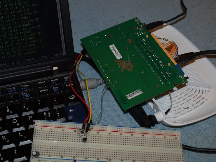
The hardware
TP-Link WL-740Nv4 is a great piece of hardware for hackers. It’s a
low end home WIFI router that can run OpenWRT. It’s based on Atheros
AR9331 SoC (which is hacking friendly as there is a lot of information
about it on Internet), has MIPS CPU clocked at 400MHz, 4MB of flash,
32MB of RAM (clocked at 400MHz). What’s most important, however, is it’s
price - you can easily buy it for about 16 USD here in Poland.
The project
I had to create cheap Ethernet based thermometer. While you can buy commercial products like this, they tend to cost more than 300 USD here in Poland. That’s strange, providing it’s so simple to create such device. I guess there’s not much demand on such devices and low production scale makes price high.
So my first though was to use Atmega or even Attiny (but there’s not
much price difference in them these days) connected to ENC28J60
Ethernet module and DS18B20 1-wire thermometer. Problem is, it has to
be cheap. Microcontroller is about 1.5 USD, Ethernet module is 6 USD, DC
power supply - 2 USD, some voltage regulator, capacitors, connectors,
Veroboard (or even a PCB), let’s say 3.5USD. That sums up to 13 USD and
we have quite a lot of soldering and we we don’t have an enclosure. At
the volume of about 250 devices, we can’t really use custom parts and I
had real problems with finding ready made enclosure.
The solution
It quickly turned out that using microcontroller will be more expensive
than using WL-740N which is full blown Linux based device with a lot
more hardware inside (while we don’t need it right now, it may be useful
in the future). I just needed 1 signal wire to control the thermometer.
There are some GPIO controlled LEDs and buttons so I though it
shouldn’t be much of a problem.
QSS button
I started with QSS button pin because I didn’t want to turn diodes off.
In order to test it, I first removed gpio_button_hotplug kernel
module, then exported and set GPIO26 as an output:
# rmmod gpio_button_hotplug
# echo 26 > /sys/class/gpio/export
# echo out > /sys/class/gpio/gpio26/direction
# echo 1 > /sys/class/gpio/gpio26/value
I was able to drive this pin without problems, driving it low with
pull-up worked too (although I had to use 10k instead of 4k7
resistor) and I was also able to read values from this pin without
problems. So I connected DS18B20 and loaded drivers:
# echo 26 > /sys/class/gpio/unexport
# insmod /lib/modules/3.3.8/wire.ko
# insmod /lib/modules/3.3.8/w1-gpio-custom.ko bus0=0,26,0
# insmod /lib/modules/3.3.8/w1-gpio.ko
and… it didn’t work. I’ve spend some time debugging it - checked all the connections, double checked pull-up resistor, connected logic analyzer and found nothing. Sensor was not responding for RESETs send by the host. I have no schematics and I’m not sure how this pin is connected to the SoC so I assumed there might me some capacitance that is preventing 1-wire to work.
WIFI diode

Round 2, let’s connect to some diode. GPIO0 sounds good. I changed my
connections, removed leds_gpio module, exported GPIO0 and did the
same tests as before. It worked so I decided to test 1-wire:
# rmmod leds_gpio
# insmod /lib/modules/3.3.8/wire.ko
# insmod /lib/modules/3.3.8/w1-gpio-custom.ko bus0=0,0,0
# insmod /lib/modules/3.3.8/w1-gpio.ko
and.. it worked too:
# ls -1 /sys/bus/w1/drivers/w1_slave_driver/*/w1_slave
/sys/bus/w1/drivers/w1_slave_driver/28-000001bcb9b3/w1_slave
# cat /sys/bus/w1/drivers/w1_slave_driver/28-000001bcb9b3/w1_slave
dc 01 4b 46 7f ff 04 10 33 : crc=92 YES
dc 01 4b 46 7f ff 04 10 33 t=25000
Great, so I soldered everything up and rebooted device to test. It
had no networking. I found out the reason after short debugging - it was
pull-up resistor. It turns out that some of the GPIO pins on the SoC re
used for boot configuration. GPIO0 is one of them - if it’s pulled
high on boot, device boots in some strange way. I wasn’t really able to
find out what’s happening since serial console wasn’t working too.
3rd round
Third time lucky, I thought. This time I started by checking all the pins capabilities:
GPIO26- QSS button (pull-up safe, OUT works, IN doesn’t work, w1 not friendly)GPIO0- WIFI diode (not pull-up safe, OUT works, IN works)GPIO13- WAN diode (pull-up safe, IN/OUT works)GPIO14- LAN1 diode (pull-up not safe, IN/OUT works)GPIO15- LAN2 diode (pull-up not safe, IN/OUT works)GPIO16- LAN3 diode (pull-up safe, IN/OUT works)GPIO17- LAN4 diode (pull-up safe, reversed logic)GPIO27- GEAR diode (pull-up safe, IN doesn’t work, reversed logic)GPIO1- QSS diode (pull-up not safe, IN doesn’t work)
I decided to use WAN diode (GPIO13) and this time everything worked as
it should. I created simple CGI script that displays temperature over
HTTP:
#!/bin/sh

echo "Content-type: text/html"
echo ""
echo '<html><head>'
echo '<meta http-equiv="Content-Type" content="text/html;charset=UTF-8">'
echo '<meta http-equiv="refresh" content="5">'
echo '<title>Temperatura</title>'
echo '</head><body>'
for f in /sys/bus/w1/drivers/w1_slave_driver/*/w1_slave; do
    cat $f | sed -rn 's/.*t=(-?[0-9]+)$/\1<br>/p'
done
echo '</body></html>'
exit 0
Conclusion
This was very quick proof of concept hack. Since I don’t really care (right now) about the diodes, I removed the driver for all of them. I could have changed it so that rest of the diodes works as they should, instead. The CGI script is not checking for CRC errors right now and checks the temperature each time we refresh the page instead of caching it.
This cheap device is great for hacking and since there are some more GPIO pins available there, I will probably do some more hacks with it in near future.